How To: Make an Arduino Shield
Two years ago, driven by a good friend of mine i decided to give it a try on timelapse photography. I had a DSLR camera but didn't had an intervalometer, so i assembled a small electronic circuit on top of an Arduino Uno, made some basic code and did my first timelapse movie. The result was awful, but for some reason I was hooked.Since that day I have never stopped looking for ways to evolve. I studied and tried various techniques until i got better. But, as i got better i felt something was missing. I needed motion control to give my timelapse movies a cinematographic feel. So, i did a market research and found out that there were great timelapse motion control devices for sell, but all of them were to expensive for me. So i had the idea to make an Arduino shield keeping in mind that i needed to control, at least, 1 dc motor, camera focus, camera shutter and for the 2 remaining axis i chose to control the Skywatcher's Acuter All in One pano head (also tested with Virtuoso Mount).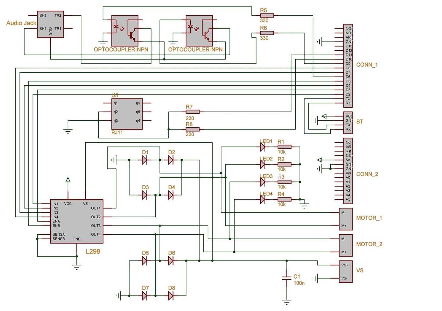
Step 1: Drawing the Schematics.Use an electronic design software and draw the following schematic.If the scheme is not clearly visible please download the pdf file.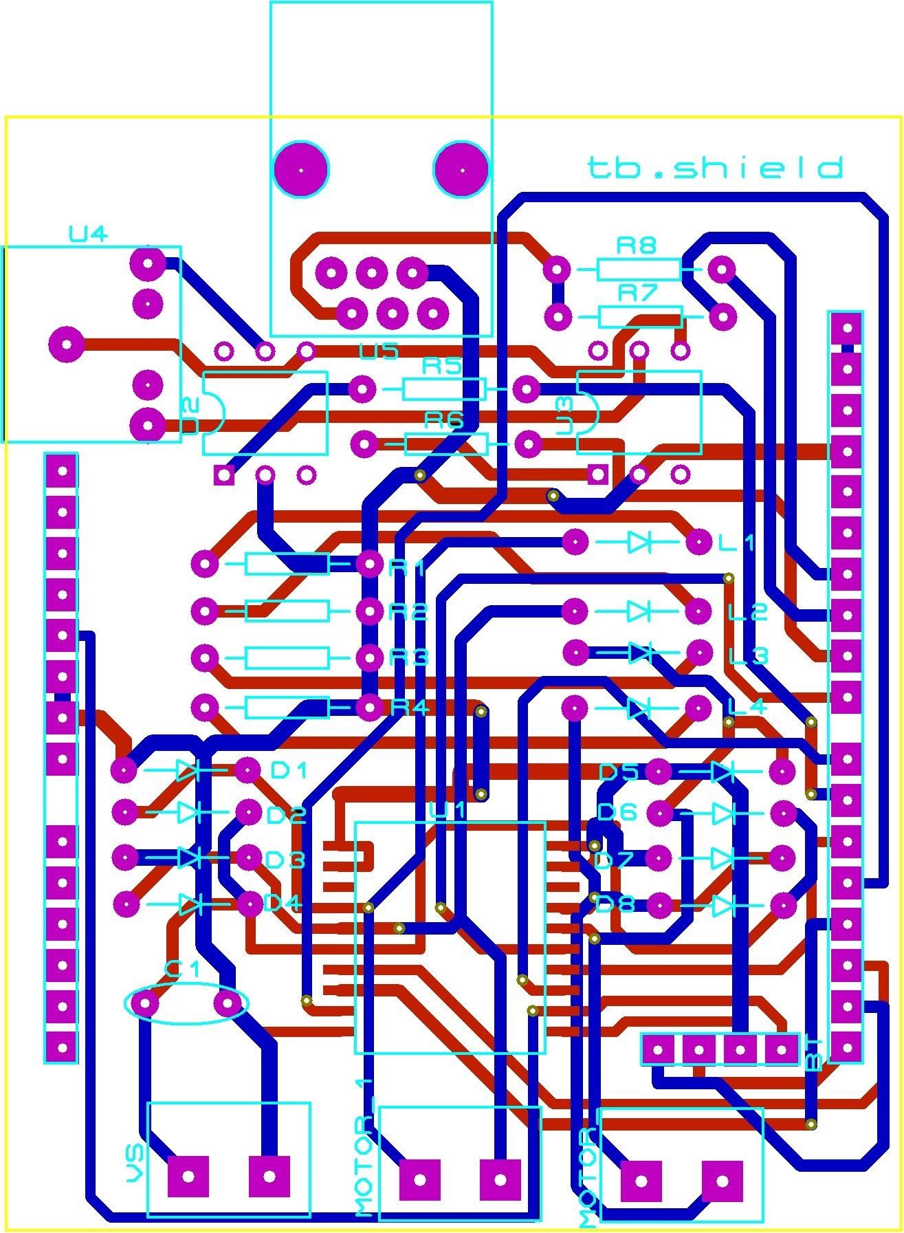
Step 2: PCBDraw the PCB layout.
Step 3: Gerber FilesMost of the electronic design softwares available will provide the ability to automatically generate the necessary gerber files to manufacture the PCB´s. If you don´t have one you can download the gerber files here: Gerber files.
Downloads |
This work is licensed under a Creative Commons Attribution 4.0 International License, which means that you can freely share, remix and make commercial use of this work as long as you attribute it to timeblocks.wordpress.com and keep the same license. I´ll update whenever I have new designs and/or code so don´t forget to like our facebook…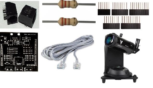
Step 4: First Test – Controlling Skywatcher Virtuoso Mount https://vimeo.com/100834758Picture of First test – controlling Skywatcher Virtuoso MountWhat you´ll need:1 x RJ11 connector 2 x 220 Ohm Resistor 2 x 8 pin Arduino Stackable Header, 1 x 6 pin Arduino Stackable Header and 1 x 10 pin Arduino Stackable Header 1 x Comunication Cable 1 x tb.shield PCB 1 x Virtuoso Mount Panohead Library and code: https://timeblocks.wordpress.com/downloads/Code:# include# includevoid setup() {panohead.init();}void loop() {long lngPositionPitch = 0;long lngPositionYaw = 0;//Read current positionlngPositionPitch = panohead.readAxisPosition(PANOHAXISPITCH);lngPositionYaw = panohead.readAxisPosition(PANOHAXISYAW);lngPositionPitch = lngPositionPitch + panohead.fromAngle(20.0);lngPositionYaw = lngPositionYaw + panohead.fromAngle(20.0);// 20 degrees motion in both axispanohead.driveToPositionBothAxis(lngPositionYaw, lngPositionPitch);delay(20000);lngPositionPitch = panohead.readAxisPosition(PANOHAXISPITCH);lngPositionYaw = panohead.readAxisPosition(PANOHAXISYAW);lngPositionPitch = lngPositionPitch + panohead.fromAngle(-20.0);lngPositionYaw = lngPositionYaw + panohead.fromAngle(-20.0);// 20 degrees motion in both axis in the opposite directionpanohead.driveToPositionBothAxis(lngPositionYaw, lngPositionPitch);delay(20000);}Now we just have to solder the RJ11 (U5 on PCB), the two 220 Ohm Resistor (R7 and R8 on PCB) and the stackable headers in the right places, connect everything and upload the code to the Arduino Board. The Virtuoso Mount should move the two axis 20 degrees in one direction and after 20 sec in the other one.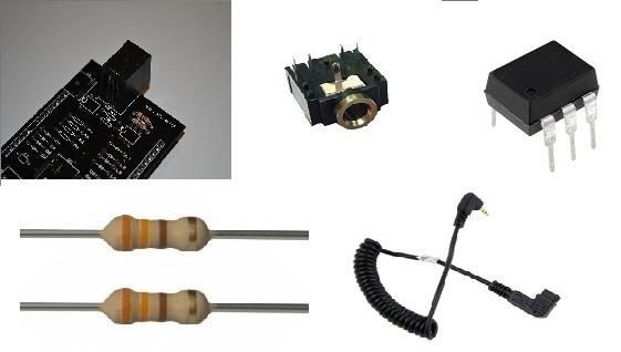
Step 5: Second Test - Controlling Camera Shutter https://vimeo.com/101553708Picture of Second test - controlling camera shutterWhat you´ll need:1 x tb.shield 1 x 3.5mm stereo audio jack 2 x optocoupler 4N25 2 x 330 Ohm Resistor 1 x release shutter cable The code: https://timeblocks.wordpress.com/downloads/# define PINFOCUS 6 // focus# define PINSHUTTER 9 // shuttervoid setup(){pinMode(PINFOCUS, OUTPUT);pinMode(PINSHUTTER, OUTPUT);}void loop(){digitalWrite(PINFOCUS, HIGH);delay(100);digitalWrite(PINSHUTTER, HIGH);delay(100);digitalWrite(PINFOCUS, LOW);digitalWrite(PINSHUTTER, LOW);delay(4800);}Now you just have to solder the 3.5mm stereo audio jack (U4 on PCB), the two optocouplers 4N25 (U2 and U3 on PCB) and the two 330 Ohm Resistors (R5 and R6 on PCB) in the right places, connect the camera to the 3.5mm stereo audio jack on the tb.shield and upload the code to the Arduino Board. The camera shutter should trigger every 5 sec.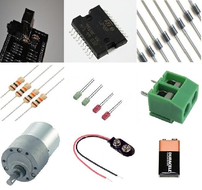
Step 6: Third Test - Controlling Motors https://vimeo.com/101917574Picture of Third test - controlling motorsWhat you´ll need:1 x tb.shield 1 x L298P 8 x diode 4004 4 x 10k Ohm Resistor 4 x 5mm led 3 x 2 pin screw connector 1 x DC Motor 1 x 9v battery adapter 1 x 9v battery The code for motor 1:https://timeblocks.wordpress.com/downloads/# define PINM1DIRECTIONFW 2 // m1 forward# define PINM1DIRECTIONRV 4 // m1 reverse# define PINM1SPEED 3 // m1 speedvoid setup(){pinMode(PINM1DIRECTIONFW, OUTPUT);pinMode(PINM1DIRECTIONRV, OUTPUT);pinMode(define PINM1SPEED, OUTPUT);}void loop(){analogWrite(PINM1SPEED, 255);digitalWrite(PINM1DIRECTIONFW, HIGH);digitalWrite(PINM1DIRECTIONRV, LOW);delay(5000);digitalWrite(PINM1DIRECTIONFW, LOW);digitalWrite(PINM1DIRECTIONRV, LOW);delay(5000);digitalWrite(PINM1DIRECTIONFW, LOW);digitalWrite(PINM1DIRECTIONRV, HIGH);delay(5000);digitalWrite(PINM1DIRECTIONFW, LOW);digitalWrite(PINM1DIRECTIONRV, LOW);delay(5000);}The code for motor 2: https://timeblocks.wordpress.com/downloads/# define PINM1DIRECTIONFW 7 // m1 forward# define PINM1DIRECTIONRV 8 // m1 reverse# define PINM1SPEED 5 // m1 speedvoid setup(){pinMode(PINM1DIRECTIONFW, OUTPUT);pinMode(PINM1DIRECTIONRV, OUTPUT);pinMode(define PINM1SPEED, OUTPUT);}void loop(){analogWrite(PINM1SPEED, 255);digitalWrite(PINM1DIRECTIONFW, HIGH);digitalWrite(PINM1DIRECTIONRV, LOW);delay(5000);digitalWrite(PINM1DIRECTIONFW, LOW);digitalWrite(PINM1DIRECTIONRV, LOW);delay(5000);digitalWrite(PINM1DIRECTIONFW, LOW);digitalWrite(PINM1DIRECTIONRV, HIGH);delay(5000);digitalWrite(PINM1DIRECTIONFW, LOW);digitalWrite(PINM1DIRECTIONRV, LOW);delay(5000);}Now you just have to solder the L298P C.I. (U1 on PCB), the 8 diodes 4004 (D1 to D8 on PCB), the 4 10k Ohm Resistor (R1 to R4 on PCB), the 4 5mm leds (L1 to L4 on PCB) and the 3 x 2 pin screw connector (VS, MOTOR and MOTOR1 on PCB) in the right places, connect everything and upload the code to the Arduino Board.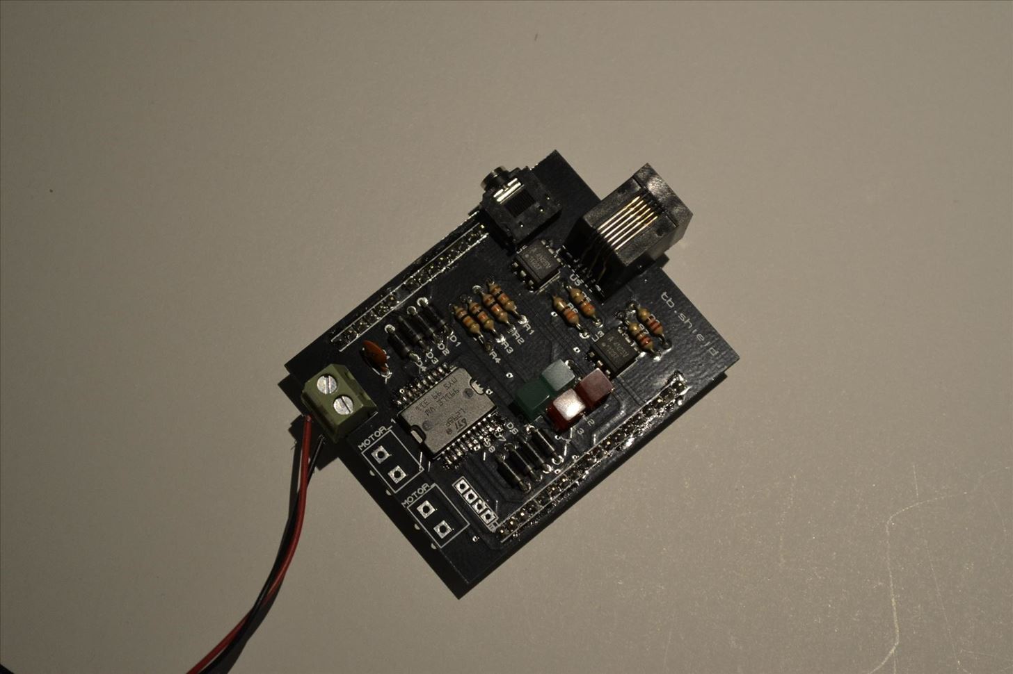
Step 7: Make Amazing Timelapse Films. https://vimeo.com/101120640Now its time to make use of your fully assembled tb.shield and start making amazing timelapse movies. I hope you enjoyed this instructable.I´ll keep it updated. Feel free to comment.Have fun,PatrÃcio
Here's How Apple Decides If You Deserve a Free iPhone Repair or Replacement. A leaked guide might make your next trip to the Apple Store a little smoother. By Sarah Rense.
Researchers at Intel and Purdue University are pursuing air-cooling technology that can make chips 200% cooler. Researchers provide a chill to fan-cooled PCs fans and heat sinks can't
What are the best ways to cool an enclosed computer cabinet
xda-developers Nexus Player Nexus Player Q&A, Help & Troubleshooting How to show photos on Nexus Player (Android TV) by kupony XDA Developers was founded by developers, for developers. It is now a valuable resource for people who want to make the most of their mobile devices, from customizing the look and feel to adding new functionality.
How to Set Up a Photo Slideshow Screensaver in Windows 7
How To Manually Remove a Virus From Your Computer Learn how to manually remove virus easily from your PC by watching this video: This guide focuses on
How to Remove a Virus (with Pictures) - wikiHow
How To: The Ultimate Guide to Playing Classic Video Games on Android How To: Connect Your PS3 Controller to Your Samsung Galaxy S3 for Better Mobile Gaming How To: Play Practically Any Old Game on Almost Any Platform with the RetroArch Emulator
[Guide+Video]How to Play Classic PC Games on… | HP TouchPad
To get camera flash notification on galaxy S9 and S9 plus, turn on camera led flash notification in Samsung S9 using below settings. Step 1: Go to settings or swipe down notification panel and tap on Settings gear icon
How to enable Flash notification in Samsung Galaxy A5-2016(SM
SSH stands for Secure SHell. It is just a protocol that allows you to access your iPhone or iPod Touch from your desktop PC or MAC and execute commands on it (thus allowing you to copy any kind of data to and from the iPhone or iPod Touch without iTunes). It's also used for a lot of
How To SSH Into Your iPod Touch 1G, 2G, iPhone 3G, 3GS Via
Thankfully, there are solutions such as AirDroid, an app that can help you with remotely managing your Android. In this guide, learn how to remotely manage your Android from a Web browser through
How To Install Official 4.4 Kit Kat Launcher On Any Android Device 4.1+ Shane Starnes. How to Upgrade / Install Android 4.4 KITKAT on Samsung Galaxy S2 Easily - Duration: 7:14.
How to Get the New Google Now Launcher on Your Samsung Galaxy
When you're checking out photos and other media on Instagram, its default bright white layout can literally be an eyesore, especially in dimly lit settings where the bleached UI feels blinding. Luckily, there's a free tweak that you can install to enable dark mode in the Instagram app for iPhone
How to get dark mode on Instagram - Quora
Netflix updated its Xbox One app, bringing a new interface users hate and cutting many features, such as voice navigation options, all gesture controls and the "continue watching" section.
Hacking NetFlix
To clear your history and cookies, go to Settings > Safari, and tap Clear History and Website Data. Clearing your history, cookies, and browsing data from Safari won't change your AutoFill information. To clear your cookies and keep your history, go to Settings > Safari > Advanced > Website Data, then tap Remove All Website Data.
Microsoft account | Microsoft Account Privacy Settings
From a desktop computer visit your settings page. Click Delete account Select a reason for removal Click Delete my account
How to delete Myspace account - YouTube
I will explain step by step how to change the soft-touch buttons behaviour on these smartphones. By default on OnePlus 3 & 3T, the left touch capacitive button works as Back button and the right button works as Recents. I'm right-handed and I prefer to have the back button on bottom-left side of a big screen phone.
Beginner: How to Switch Among Open Apps on Your Android Device
0 comments:
Post a Comment